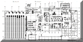
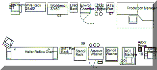
Drawing The Micro Layout
How to Prepare Detail Plant Layout Drawings
The Approach
The micro or detail layout is approached by taking one Space Planning Unit (cell, activity area, department) at a time and considering it as in independent project. If the macro-layout was done well, few difficulties will arise.
Product-focused workcells require the most analysis and effort. For these types of SPU refer to our pages on Workcell Design.
Functional SPUs such as a maintenance department, may require only a list of equipment and furniture. It then becomes a matter of placing the various pieces within the allotted space while accommodating traffic and other considerations. In other situations, a process chart for that part of the process internal to the SPU will be helpful.
Hints for Drafting
Setup Layers
The following minimum set of layers is recommended. Beyond this minimum set, layer management depends largely on individual experience, convenience and the situation.
TITLE BLOCK LAYER--contains the title block and borders. This layer is off during the drawing activities but should be on for printing.
BUILDING LAYER-- This layer contains column centerlines, columns, permanent walls and other features that are unlikely to change.
GRID LAYER-- This layer consists of markers or points on (usually) 1' centers. It is most useful when making prints for installation. In most instances, the installers work by scaling the drawing using the grid points rather than explicit dimensions.
MACRO-LAYER-- This layer shows the macro-layout. It can be turned on or off during the detail layout work.
MICRO-LAYER(S)--this layer is where most objects are placed. There may be several such layers.
Establish Reference Lines
The usual reference line are column centerlines and the inside surface of permanent walls. They are usually on the original architect's drawings when such drawings are available. If the building was designed on a CAD system, the CAD drawings are usually reliable. For older buildings each dimension should be verified with field measurements. Check & double check these dimensions.
Draw Equipment Templates
Draw templates for all items of furniture or equipment that require floor space. The outside dimensions of templates should be accurate within +/- 1". Interior features of equipment usually needs only pictographic representation that suggests the appearance of the actual machine. Store the templates as blocks or groups within the CAD system. Labels should identify the type of equipment.
Dimensioning
Most layout drawings have few dimensions. Rather, they are drawn to scale and printed to a scale that can be measured easily when equipment and furniture is placed.
■ ■ ■ ■ ■ ■ ■


